Electric motors represent a crucial component of modern technology, acting as converters of electrical energy into mechanical motion through the rotation of a rotor along a fixed axis. These dynamic devices play a pivotal role in a myriad of applications such as surveillance cameras, intelligent locking systems, and additive manufacturing machines. Both professional engineers and enthusiasts must grasp the nuances among various motor types, as each motor not only influences the final application but also guides the selection of suitable motor drivers.
In this discourse, we will delve into two prevalent motor categories and their corresponding motor control systems: stepper motors and DC motors. This exploration aims to elucidate the similarities and disparities between these motor variants while presenting specialized driver modules for stepper and DC motors, enabling seamless control and performance optimization.
Understanding Stepper Motors: An In-depth Analysis
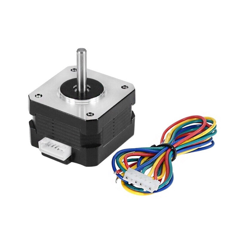
Stepper motors work by converting electrical impulses into explicit mechanical movements. Their operation is based on distinct steps which make them highly accurate and controllable. Each step reflects an exact angle of rotation, generally around 1.8°. The number of rotations is directly proportional to the number of electrical pulses received, thus making the movement of these motors precise and predictable.
Here’s a breakdown of the key components of a stepper motor:
- Rotor: This part, affixed to the motor shaft, is responsible for rotation in the stepper motor. The rotor carries teeth or magnetic poles which, when they interact with the stator, generate movement;
- Stator: This is a stationary part of the motor. It contains wire coils capable of producing magnetic fields. These coils are arranged into groups referred to as phases;
- Winding Phases: Stepper motors are classified as either bipolar or unipolar based on the winding phases they have. Bipolar stepper motors contain two winding phases, while unipolar stepper motors have four. Each phase links to a winding on the stator;
- Pulses and Control: In order to turn the stepper motor, a certain order of electrical pulses should be directed to the winding phases. The order and timing of these pulses are critical in determining the direction and the length of each step.
One of the most alluring attributes of stepper motors is their high precision due to their step-by-step movement. Besides, they are engineered to optimize their holding torque, which demands maintaining a top-notch current. This feature makes stepper motors an excellent choice for holding position tasks, including robotics and camera gimbals, among others. Their level of precise control and strong holding capability pushes their usability to new heights. Also, discover the magic behind stepper motor’s working principle and how it powers precision movements in machines. Unlock the secrets today!
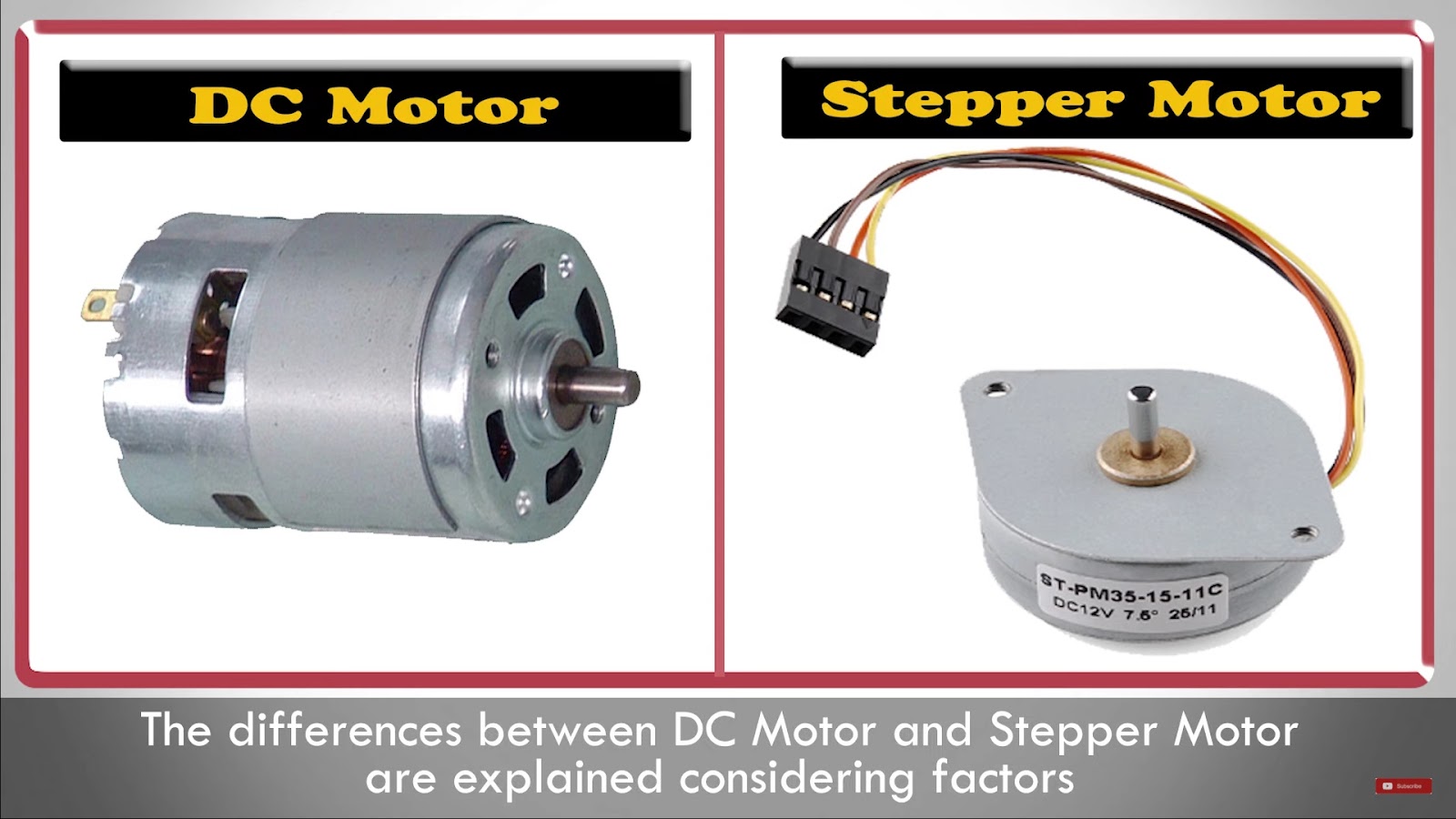
Stepper Motors Vs. DC Motors: A Comparative Analysis
Brushed DC motors, brushless DC (BLDC) motors, and stepper motors are all unique types of electric motors with varying strengths and drawbacks. Every motor type is especially adept at certain applications due to these differences. Here we outline some of the major distinctions between these motors, particularly concerning their operation and controllability.
Operational Attributes and Control Mechanism
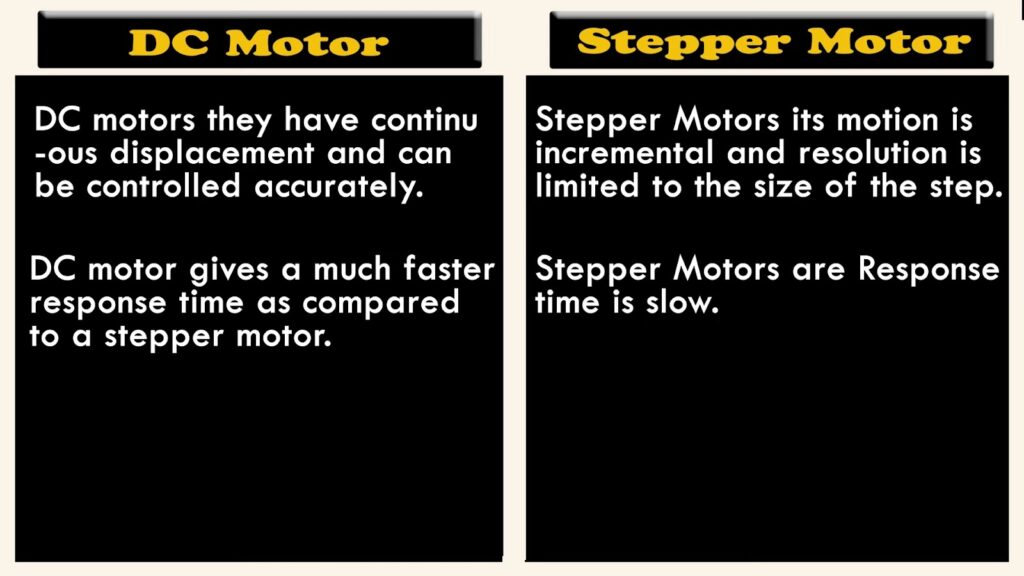
- Stepper Motors: These motors work effortlessly within an open-loop system. The specific location of a stepper motor is directly related to the accurate number of steps or pulses sent to the motor. As stepper motors run on definitive and easily measurable steps, there’s no requirement for maintaining position feedback. Nonetheless, an external device such as a microcontroller (MCU) is necessary to adjust the run direction and speed of the motor. Applications: Stepper motors are most appropriate for jobs requiring precise positioning and speed control. They’re commonly found in 3D printers, CNC machines, and automated picking systems.
- Brushed DC Motors: A DC power supply powers these motors, which is attached to the rotor through carbon brushes. Simple brushed DC motors allow control via an open-loop system, while more complex variants might need feedback systems. Normally, these motors don’t need external controllers and their adjustment is easy. For instance, altering the motor’s voltage adjusts its speed. Applications: Brushed DC motors are ideal for applications where ease of control and low initial cost are paramount. You’ll find them in home appliances, automotive applications, and tools.
- BLDC Motors: BLDC motors mandatorily function in closed-loop systems. This provides them with high precision, but also necessitates extra control circuitry for seamless operation. Applications: BLDC motors are often used in applications where efficiency, reliability, and noise minimization are crucial, such as in drones, electric vehicles, and HVAC systems.
In conclusion, whether it’s a stepper motor, brushed DC motor, or a BLDC motor, the choice will depend significantly on the specific requirements of the application. Understanding these motor types will certainly contribute to making an informed decision.
Durability and Maintenance: Stepper Motors vs DC Motors
Understanding the lifecycle and maintenance needs of different types of motors is vital in choosing the right option for a particular application. The longevity of a motor and its maintenance demands can drastically affect the total cost and effectiveness of various applications.
Stepper Motors: Long Life and High Reliability
Stepper motors are esteemed for their straightforward design, durability, and significantly high lifespan. They can serve relentlessly for 4 to 5 years or approximately 10,000 hours, making them a steadfast choice for long-term applications. The sturdy construction and absence of brushes reduce the risk of mechanical failure and make stepper motors a reliable option for many industries.
Brushed DC Motors: Maintenance Required
While brushed DC motors are also relatively dependable, they demand continuous upkeep due to the brushes’ wear and tear. These motors generally last for a few thousand hours before the need for maintenance surfaces. The brushes in these motors are in constant contact with the commutator, leading to eventual wear and thus necessitating periodic replacements to prevent motor failure.
Brushless DC Motors: Extended Lifespan with Lower Wear and Tear
Brushless DC motors, as the name suggests, eliminate brushes, thereby reducing mechanical wear. This feature significantly extends their lifespan beyond that of their brushed counterparts. These motors can smoothly operate over 10,000 hours without needing major maintenance, making them a highly resilient option.
It’s clear that each motor type has a different lifecycle and maintenance demands. Assessing these alongside the operational requirements can guide the right choice of motor for any task. Whether you need a robust stepper motor that provides high precision, a well-balanced brushed DC motor, or a durable and efficient BLDC motor, understanding their lifecycle will ensure the chosen motor meets the longevity and maintenance expectations.
Balancing Efficiency and Noise: Stepper Motors vs DC Motors
Assessing the efficiency and noise generation of various motors is crucial to determining their suitability for specific applications. Here’s a comparison of stepper motors, brushed DC motors, and BLDC motors in terms of these key aspects.
Stepper Motors: Energy-Intensive and Noisy
While stepper motors are highly precise, their efficiency can be a concern due to high energy consumption and heat generation. These motors operate at their maximum current all the time, causing substantial energy loss through heat dissipation. This heavy-duty operation also makes them the noisiest among the motor varieties. The distinct stepping action of these motors produces a characteristic whirring or ratcheting sound, and while this might not be noticeable in loud industrial environments, it can be disruptive in quieter settings.
Brushed DC Motors: Less Noisy, But Efficiency Varies
Brushed DC motors tend to be more efficient than stepper motors as they don’t always operate at their peak current. However, the presence of brushes can result in some energy loss due to friction. In terms of noise, the contact of brushes with the commutator while rotation does produce some noise, but it’s less pronounced compared to stepper motors.
Brushless DC (BLDC) Motors: High Efficiency, Low Noise
BLDC motors stand out as the most efficient in this comparison. Without brushes, these motors experience minimal friction, reducing energy losses and enhancing efficiency. When it comes to noise generation, BLDC motors are the quietest due to the absence of brushes and commutator interaction. This makes them a great choice for applications where noise reduction is critical.
To sum up, choosing the right motor type requires balancing efficiency, noise generation, and other factors such as the intended application, durability, and lifecycle requirements. While stepper motors have their charm in precision and holding torque, brushed DC motors offer moderate efficiency and quieter operation. Meanwhile, BLDC motors stand out for their superior efficiency and minimal noise, making them an excellent choice in many modern applications.
Comparison of Stepper, Brushed DC, and BLDC Motors
| Motor Type | Advantages | Disadvantages | Applications |
|---|---|---|---|
| Stepper Motor | High accuracy, High precision, Easy to control, Long lifespan (10,000 hours) | Less efficient, Requires external control (microcontroller), Noisy | 3D printers, Telescope, Disk drives, Robotics |
| Brushed DC Motor | Moderate efficiency, Faster response time, Can detect overload conditions | Shorter lifespan; require maintenance, Complex control | Electric tools/appliances, Automotive (e.g., windshield wipers), Toys, Fans |
| BLDC Motor | High efficiency, Requires little maintenance, Quiet, Very long lifespan (10,000+ hours) | Complex control, Susceptible to extreme temperatures | Electric vehicles, Household appliances, Medical devices (e.g., infusion pumps, imaging) |
The Role and Importance of Motor Driver ICs in Operating Motors
Motor Driver ICs are integral components in managing motor operations. These specialized integrated circuits, simply referred to as motor drivers, serve as the fundamental control units in motor systems. They regulate key operational aspects such as the speed, direction, and various other parameters that are vital for efficient and reliable motor functioning.
Motor drivers perform multiple roles including:
- Amplifying Electrical Signals: Motor drivers enhance the electrical signals used to power and manage the motor, ensuring optimal operation;
- Speed Regulation: These ICs facilitate precision control over the speed of the motor, enabling varying speeds to cater to different operational needs;
- Built-In Protection Features: Motor drivers are often built with robust protective functionalities such as Over-Current Protection (OCP) and Over-Temperature Protection (OTP). This ensures long-term durability and safety against electrical and thermal damages.
MPS is a renowned provider of both stepper motor drivers and brushed DC or BLDC motor drivers, compatible with a range of motor types. Detailed elaboration on a few exemplary motor driver ICs from MPS are provided in subsequent sections. These discussions intend to give a comprehensive understanding of how these ICs work and the beneficial features they bring to motor operation.
MPS’s Innovative Stepper Motor Drivers: The MP6605 Series
The versatile MP6605 series from MPS, comprised of the MP6605C, MP6605D, and MP6605E, is engineered specifically for unipolar stepper motors. These 4-channel low-side driver ICs are equipped with integrated low-side MOSFETs (LS-FETs) and high-side clamp diodes that ensure smooth motor operation.
The MP6605 series boasts a broad input voltage range spanning from 4.5V to 60V. These high-performing ICs are housed in compact QFN-24 (4mmx4mm) packages, making them suitable for integration in space-conscious designs. The robust ICs can support an output current of up to 1.5A.
To uphold device integrity and longevity, the MP6605 series comes with extensive protective features such as:
- Over-Current Protection (OCP);
- Over-Temperature Protection (OTP);
- Under-Voltage Lockout (UVLO).
The UVLO feature prevents the IC from operating under conditions of insufficient input voltage, effectively shielding the device from potential damage.
The key distinction among the MP6605C, MP6605D, and MP6605E lies in their control interfaces:
- MP6605C: This IC utilizes an I2C interface for effective control;
- MP6605D: This version employs a parallel interface whereby each output is controlled by individual input pins;
- MP6605E: This model utilizes a serial (SPI) interface, which enables simultaneous data transmission to the IC’s outputs and readings from the sensor inputs.
These varying interface options provide flexibility, allowing users to choose the variant that best suits their specific requirements and motor control preferences.
Rethinking Motor Efficiency: MPS’s Brushed DC Motor Drivers – The MP6612 Series
MPS’s MP6612 family broadens the horizons of motor driver innovation by introducing an H-Bridge driver specially tailored to manage reversible loads. Engineered with remarkable flexibility, the MP6612 can proficiently control a DC motor, a stepper motor winding, and other load types.
Its operation revolves around the IN1 and IN2 pins, extending an additional layer of flexibility to its functionality. The MP6612 emphasizes energy efficiency by maintaining a low quiescent current (IQ) when set in brake mode, thus minimizing unnecessary power consumption during idle or inactive periods.
As with all MPS’s offerings, the MP6612 extends a comprehensive suite of protective features, including Over-Current Protection (OCP), Over-Voltage Protection (OVP), and Over-Temperature Protection (OTP). These mechanisms safeguard the system against potential hazards, promoting consistent performance and longevity. To enhance system diagnostics, the MP6612 integrates fault indicators for these protective mechanisms, enabling real-time monitoring and fault detection.
In addition to its robust features, the MP6612’s availability in a TSSOP-20 package facilitates enhanced thermal management, a critical aspect of efficient and reliable motor operation.
Other notable members of the MP6612 family include:
- MP6612D: This IC incorporates a current-sense circuit, granting the ability to provide an output voltage (VOUT) proportionate to the load current. This feature allows precise current monitoring, ultimately enhancing the overall control and efficiency of the motor system;
- MPQ6612A-AEC1: This variant is a Q100 grade 1 automotive-rated counterpart to the MP6612 and MP6612D. With its automotive-grade capabilities, the MPQ6612A-AEC1 is ideal for use in automotive applications such as electronic door handles and locks, bringing the reliability and performance of the MP6612 series to the automotive industry.
Pioneering Motor Management: MPS’s BLDC Motor Drivers – The MP6546 Series
MPS’s MP6546 series stands at the forefront of Brushless DC motor driver technology. This 3-phase BLDC motor driver features an I2C interface that facilitates adjustable parameters such as operational modes, protective mechanisms, and angles. It adopts field-oriented control (FOC) logic and precise angle calculation methods to ensure meticulous motor operation.
The MP6546 extends comprehensive fault indication measures for Over-Current Protection (OCP), Under-Voltage Lockout (UVLO), Over-Voltage Protection (OVP), and Short-Circuit Protection (SCP). As such, the device is shielded against over-current conditions and other potential risks that could compromise its function.
One of the distinguishing features of the MP6546 is its compatibility with a multi-slave mode, where it can seamlessly function with three-axis gimbals attached to a singular I2C interface bus. Each slave unit within this setup possesses the capacity to calculate its own angle and control the motor via the I2C interface. This enhances the overall system’s versatility and scalability.
The MP6546 carries the flexibility further by supporting both magnetic angle sensor input mode and linear Hall-sensor input mode. As a result, it can handle both position feedback methods:
- Magnetic Angle Sensor Input Mode: In this mode, the MP6546 synergistically operates with MPS’s MagAlpha magnetic angle sensor family, allowing for optimal tracking and reporting of the motor’s angle;
- Linear Hall Sensor Input Mode: When operating in this mode, the MP6546 conveys its HA and HB signals to an Analog-to-Digital Converter (ADC). The digital core can then compute the motor’s angle based on the processed data.
The MP6546’s configurability underscores its high versatility, making it a suitable choice for diverse systems without necessitating extensive additional work or adjustments. Whether for industrial, automotive, or consumer applications, the MP6546 is engineered to deliver reliable and efficient motor control.
Conclusion
In conclusion, electric motors are indispensable devices that efficiently convert electrical energy into mechanical motion, playing a critical role across diverse applications. Understanding the distinctions between motor types, such as stepper motors and DC motors, is essential for engineers and hobbyists alike, as it directly influences motor driver selection and application performance. By leveraging specialized motor drivers tailored to each motor type, seamless control and optimization can be achieved, further enhancing the functionality and efficiency of motor-driven systems in various technological domains.