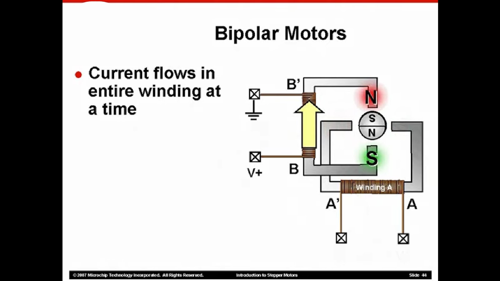
In today’s advanced technological age, stepper motors have gained widespread popularity thanks to their exceptional open-loop position control capabilities. These motors are tailored to meet precise criteria to guarantee a seamless output torque during their rotational movement. The stability of rotation is intricately tied to both the physical design of the motor and the mode of control implemented. This piece delves into the intricacies of the bipolar stepper motor, shedding light on its structural composition and various control modes.
Understanding the Bipolar Stepper Motor: A Detailed Look at its Core Components
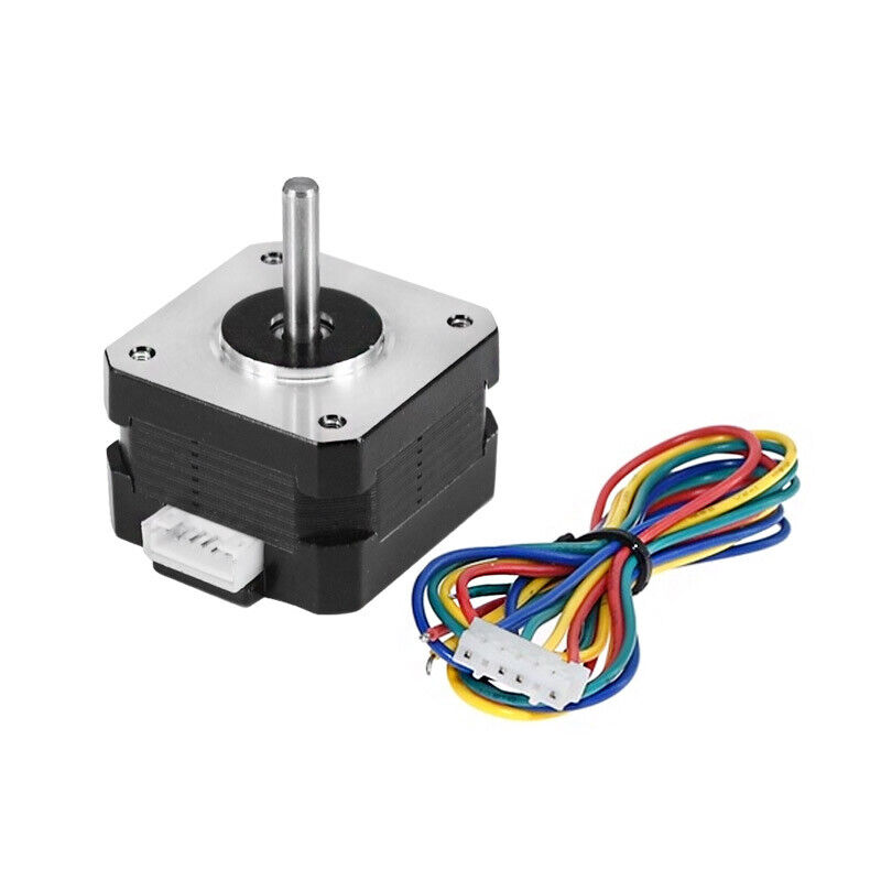
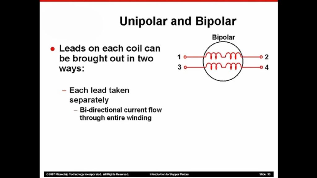
Bipolar stepper motors are a subtype of brushless DC (BLDC) motors, distinct for their ability to break down their rotations into equal steps. They’re identified by a single winding per phase, and as such, are two-phase, four-wire stepping motors. These motors are principally made up of two key parts: the stator and the rotor.
Dissecting the Stator: The Non-moving Component
The stator, true to its name, is the non-moving, stationary part of the bipolar stepper motor. This part consists of 8 cores, each wound with a specific pattern of windings and having five teeth. The windings for Phase A commence from the first stator, stretching to stators 3, 5, and 7 successively.
Take note of the winding directions: stators 1 and 5 wind in one direction, and stators 3 and 7 in another, creating a balanced, mirror-like setup where two groups (stators 1 and 5, and stators 3 and 7) have opposite winding directions.
The Principle of Phase B Windings
Much like Phase A, Phase B’s windings follow a similar pattern. Here, stators 4 and 8 form one group, while stators 2 and 6 form another. This setup ensures a balanced operation, similar to the construction of Phase A windings.
Bipolar stepper motors, with their unique construction and operation, offer precise control and efficient performance. Understanding their fundamental components – the stator and the rotor – and the winding principles gives you a solid foundation to fully grasp their function and potential applications. Whether you are an electronics enthusiast, a budding engineer, or a seasoned professional, a deep knowledge of these motors can expand your toolkit for various projects and applications.
Probing the Rotor: The Heart of a Bipolar Stepper Motor Movement
When delving into the mechanics of bipolar stepper motors, one cannot overlook the crucial role played by the rotor. Unlike its stationary counterpart, the stator, the rotor brings mobility and precision to motor operations. Let’s unravel the fascinating intricacies of the rotor and its magnetic components.
- Magnetized Perfection: The rotor is equipped with an axially magnetized permanent magnet, a core element that sets the stage for magnetic interactions within the motor. This magnetization, characterized by its magnetic lines of force, creates a compelling force field within the motor’s structure;
- Locking Torque Marvel: A standout feature of bipolar stepper motors is their locking torque capability. This magnetic marvel is made possible by the magnetoresistance effect and the magnetic lines of force generated by the permanent magnet. Even in the absence of external power, stepper motors exhibit a remarkable ability to maintain a static position, making them ideal for applications requiring precise positioning;
- Structural Symphony: Understanding the structural composition of the rotor provides deeper insights into its functionality. The rotor’s teeth are strategically aligned in opposition to the stator gear, typically boasting around 50 teeth. This arrangement, combined with the motor’s phase structure, contributes to the motor’s step angle precision;
- Step Angle Precision: The step angle, often set at 1.8 degrees, signifies the mechanical rotation achieved by the rotor during an electrical cycle completing 90 degrees. This precision is paramount for ensuring accurate and controlled movements in various applications.
Key Insights and Recommendations:
- Precision Considerations: When selecting a bipolar stepper motor for applications demanding highly controlled movements, evaluating the step angle precision becomes paramount. Opting for motors with finer step angles enhances accuracy and performance;
- Utilize Locking Torque: Leverage the locking torque feature in applications where maintaining a static position without continuous power is essential. This feature adds an extra layer of stability and reliability to your system;
- Diagnostic Advantage: A comprehensive understanding of the interplay between the stator and rotor aids in diagnosing issues and troubleshooting motor-related problems efficiently. This knowledge empowers engineers to optimize motor performance and longevity;
- Performance Evaluation: Assessing factors such as the number of teeth, phase structure, and rotor arrangement facilitates informed decisions regarding motor selection. Each parameter influences the motor’s performance and suitability for specific applications, ensuring optimal functionality and efficiency.
Delving into Stepping Modes: The Heartbeat of Bipolar Stepper Motors Operation
Essentially, the structure of the bipolar stepper motor is designed for simplicity and efficiency. It functions differently from other motors through a unique method called a dual full-bridge drive. This method allows for a more straightforward understanding of the motor’s control methods, as the stator and rotor can be conceptually reduced to possess a single tooth.
In this setup, the winding of phase A connects to the first full-bridge drive, while phase B winding is linked to the second full-bridge drive. The bipolar stepper motor primarily operates under three distinct control modes:
- Single-Phase Step;
- Full Step;
- Half-Step.
The Single-Phase Step
In the single-phase step mode, only one phase – either phase A or B – energizes at a time. This mode is known for its low power consumption, making it a smart choice for applications where energy efficiency is a dominant concern.
The Full-Step Mode
The full-step mode operates by energizing two phases simultaneously. This mode provides higher torque than the single-phase step, making it suitable for applications requiring a stronger rotational force.
The Half-Step Mode
The half-step mode is an intermediate mode that combines the best of both worlds. It alternates between energizing a single phase and two phases, effectively doubling the steps per revolution and enhancing resolution.
Useful Tips and Recommendations
- The choice of stepping mode largely depends on the specific requirements of the application the motor is being used for;
- If reducing power consumption is a top priority, using the stepper motor in single-phase step mode is a wise choice;
- For applications needing higher torque, it’s recommended to operate the stepper motor in full-step mode;
- To achieve higher resolution, consider running the motor in half-step mode;
- Understanding these operational modes can aid in troubleshooting motor problems and optimizing performance in various applications.
Deviating the Conventional: Unveiling Single-Phase Stepping
Single-Phase Stepping is a unique operational mode where only one out of the two phases (Phase A or Phase B) is energized at a time. This mode plays a significant role in propelling the movements of the bipolar stepper motor, leveraging the law of magnetic attraction and repulsion. A closer look at the signals and rotor positions is needed to comprehend this stepping type.
Traversing through the Single-Phase Stepping Process
The transitioning process of the single-phase stepping can be thought of as a dance involving three steps. Each step corresponds to a unique combination of energization and rotor positions.
Step 1: Energizing Phase A
The journey begins with energizing Phase A. The energy current flows from the Q1 to Q4 terminals. This energization results in Stator A aligning its upper end towards the North Pole (N) while its lower end towards the South Pole (S). Consequently, the rotor promptly rotates to position 8, aligning itself with the magnetic field generated.
Step 2: Shifting to Phase B
Phase A takes a rest, and it’s Phase B’s turn to energize. The drive current now creates a route from Q5 to Q8. Due to this change, one end of Stator B repositions itself towards the South Pole while the other end points the North Pole. This directional shift creates a magnetic ripple, effectively causing the rotor to turn to position 2.
Step 3: Reinvigorating Rotor Movement
The final step involves restarting the sequence, which triggers the rotor to commence rotation. This rotation is not a random movement. Instead, it follows a pattern determined by the sequencing of Phase A and Phase B energization, thereby leading to a predictable and controlled motor movement.
Key Recommendations and Advices
- An understanding of the energization sequence and rotor movements in single-phase stepping enables better control and customization of motor performance;
- Single-phase stepping is a power-efficient choice for applications that don’t require high torque;
- For troubleshooting issues with motor motion or unusual noise, consider checking the energization sequence for potential issues;
- The ability to understand and manage single-phase stepping can significantly improve a hobbyist’s or engineer’s ability to utilize bipolar stepper motors effectively in different applications.
Unfolding Full-Step Stepping: A Leap Beyond Single-Phase Stepping
Full-Step Stepping distinguishes itself from the Single-Phase Stepping by utilizing both Phase A and Phase B windings concurrently. This dual activation allows for a broader range of rotation and produces higher torque, making the Full-Step Stepping mode a potent solution for applications that demand stronger motor force.
Walking Through the Full-Step Stepping Process
This intriguing stepping process houses four distinct phases of motor operation, each associating with a specific energization state and a rotor position. The rotation of the rotor, in this case, is hinged on the predetermined start-up sequence.
Phase 1 & 2: Simultaneous Energization
The first two phases involve powering up of both Phase A and Phase B. The driving current flows through the windings of these phases, creating a potent magnetic field. This field compels the rotor to settle at a position that is in alignment with the field, thereby initiating the rotation.
Phase 3 & 4: Sequential Deactivation
In the last two phases, the motor begins to curtail the current supply to Phase A while Phase B remains energized. This shift creates a magnetic asymmetry which induces the rotor to reposition itself in alignment with the active field. As the process loops back to the first phase, the motor exhibits a continuous and seamless motion.
Ensuring Optimal Performance: Tips and Recommendations
- Full-Step Stepping is ideal for applications that demand greater torque. Know your application requirements before selecting the stepping mode;
- Pay attention to the full-step current waveform as it can provide valuable insights into the motor’s performance and possible issues;
- A deep understanding of Full-Step Stepping sequence can help in troubleshooting and optimizing motor performance;
- Adopt Full-Step Stepping mode when precision is not the absolute requirement, and greater torque is beneficial for the operation;
- Try experimenting with different start-up sequences to explore how they affect the rotation of the rotor in Full-Step Stepping mode.
Read about the nuances of stepper motors vs. DC motors in this insightful article. Discover the key distinctions and make informed decisions for your projects!
Half-Step Stepping: The Best of Both Worlds
As its name suggests, Half-Step Stepping is a stepping mode that walks the line between Single-Phase Stepping and Full-Step Stepping. This mode cleverly alternates between the two stepping types to offer more granular control over the rotor’s movements. This feature results in smoother rotation, making Half-Step Stepping an excellent choice for applications requiring more fluid movements.
Diving into the Half-Step Stepping Process
The Half-Step Stepping process is an orchestrated sequence involving eight different steps. These steps form a cycle where the modes of operation alternate between Single-Phase and Full-Step Stepping.
Steps 1 & 2: Kickstarting the Single-Phase Step
The cycle commences with activating Single-Phase Stepping. Here, only Phase A or Phase B winds up, causing the rotor to align with the magnetic field. This step ensures that the rotation starts smoothly.
Steps 3 & 4: Transitioning to Full-Step
Next, the process smoothly transitions to Full-Step Stepping. Both Phase A and Phase B get activated simultaneously, providing a much-needed torque boost.
Steps 5 to 8: Looping the Cycle
As the cycle progresses, it loops back to Single-Phase Stepping, then back to Full-Step, and so on. This sequenced variation ensures that the Half-Step Stepping mode achieves a balance between smooth rotation and enhanced torque.
Enhancing Motor Performance: Tips and Insights
- Half-Step Stepping is an excellent choice for applications that require both fluid movements and a considerable amount of torque;
- Understanding the alternation between Single-Phase and Full-Step modes in Half-Step Stepping leads to better control over the motor movements;
- Observe the current waveforms during Half-Step operation as it can provide insights into the motor’s performance and possible issues;
- Half-Step Stepping can be a useful diagnostic tool for pinpointing problems. If a motor performs poorly in other stepping modes but works well in Half-Step mode, this can indicate potential issues with the torque.
Overview of Stepping Modes in Electric Motors: Sequences and Positions
| Stepping Mode | Sequence | Electrical Stepping Position |
|---|---|---|
| Single-phase step | A > B > A > B | 8 > 2 > 4 > 6 |
| Full step | A+B > A+B > A+B > A+B | 1 > 3 > 5 > 7 |
| Half-step | A+B > B > A+B > A > A+B > B > A+B > A | 1 > 2 > 3 > 4 > 5 > 6 > 7 > 8 |
In this table, each step sequence is shown with its progression and the corresponding electrical stepping position. The symbols “A” and “B” represent the activation of different phases in the motor, and the overline (¯¯¯¯) indicates the deactivation of that phase.
Conclusion
In conclusion, the evolution of stepper motors in the intelligent era has revolutionized various industries, offering unparalleled open-loop position control performance. With specific design requirements ensuring smooth output torque and rotational stability, these motors continue to be a cornerstone in modern automation and control systems. The focus on bipolar stepper motors in this article has provided insights into their structural intricacies and diverse control modes, showcasing their versatility and efficiency in meeting a wide range of application needs.