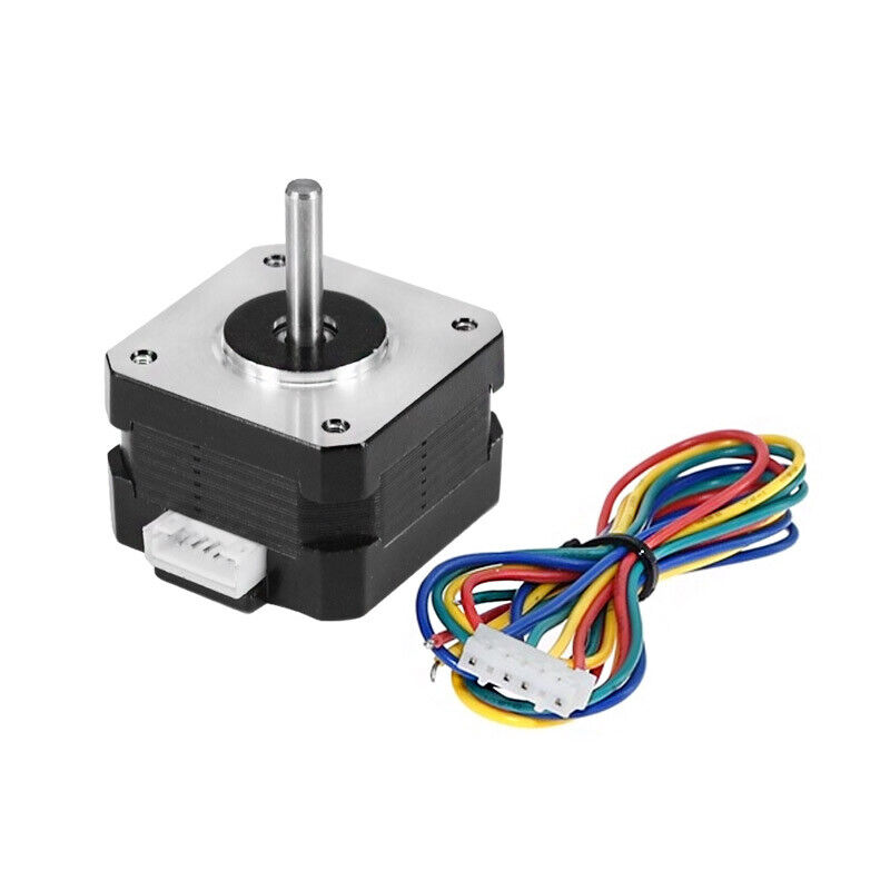
A stepper motor, very simplistically, is a motor with a rotor in which a permanent magnet is fixed and a stator with several electromagnet windings. The permanent magnet rotates the rotor in accordance with the magnetic field created by the direct current in the stator, so by supplying current pulses to the windings in a certain order and polarity, it is possible to achieve rotation of the magnetic field, followed by the rotor in the right direction at the right speed.
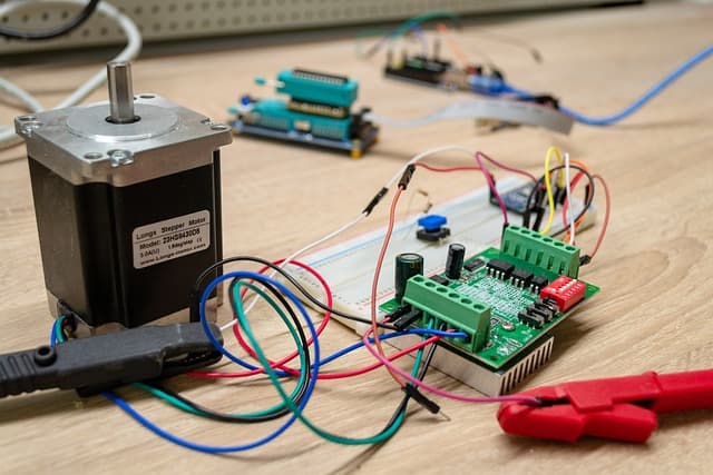
The magnet engagement can be controlled directly by microcontroller commands. Low-voltage stepper motors work directly from pins or by means of shift registers, for high-power and high-voltage stepper motors you will need to build a rather complex power H-bridge for two coils and open signals in pairs of those or transistors.
That’s all well and good, but this approach has a few drawbacks. You need an H-bridge with precisely calculated parameters, TTL transistors, induction protection, and other engineering solutions. You need a minimum of four pins to control one motor, if the motor is bipolar on two windings. 3D printers are known to have a minimum of 4 stepper motors, which means finding 16 free pins can be a problem. From the first comes the second disadvantage – increased load on the computational resource, which is already fully utilized on printers.
It would be possible to tell the motor when and at what moment to make a step. This possibility is provided by the hero of our article – stepper motor driver.
A stepper motor driver is an electronic device that controls the motor windings, guided by commands from a microcontroller. A driver can be designed in different ways, but any driver has a few mandatory elements. Input: two signals, DIR – direction and PUL – command to execute a step, output: two contacts on one coil, called “A”, and two on the second – “B”. What happens inside the driver is a great mystery covered by the developers, but at the output we get what we need – power pulses to the motor windings.
Otherwise, different drivers may have differences, and serious ones, for example, in terms of allowable voltages and current strength. The simplest versions of drivers have no settings and work according to a minimal algorithm, like the one shown in the first picture: the windings are switched on, alternately reversing polarities. In this case, the rotation is jerky, noisy, but most importantly, it does not provide maximum torque.
For more powerful and smooth rotation, the motor works in so-called “half-steps”. Intermediate positions appear between the main positions, when both windings are switched on simultaneously in the correct order.
More complex variants are also possible, in which different voltage levels are applied to the winding pairs, thus dividing the half-step into several gradations. The oscillogram of “multistep” operation is much more complex and represents four broken step lines in a bizarre way. Signal algorithms vary from manufacturer to manufacturer, there are more successful ones, and there are smaller ones. But one thing is certain, the more gradations of pitch, called “microsteps”, the smoother and quieter the motor runs. Providing the motor with half steps and microsteps is also the driver’s task, the controller doesn’t need to keep track of it. Taking into account that there can be up to 256 such gradations for each step, we can conclude that drivers make the controller’s work tens and hundreds of times easier, while providing smooth and continuous motor control.
Some drivers are capable of additional tricks, for example, regulation of current power depending on the load on the rotor, which saves energy and reduces heating of the driver and motor, as well as other useful and not so useful things.
Some drivers initially strictly adhere to one single algorithm of operation, while others are able to change parameters: power, number of half-steps and other settings by program commands or hardware switches.